Erfahrung beim Biegen von Blechen
A: Tonnage der Biegemaschine
Während des Biegevorgangs wird die Kraft zwischen der oberen und der unteren Matrize auf das Material ausgeübt, wodurch sich das Material plastisch verformt. Die Arbeitstonnage bezieht sich auf den Biegedruck während des Biegens. Die Einflussfaktoren für die Bestimmung der Arbeitstonnage sind: Biegeradius, Biegemethode, Formverhältnis, Bogenlänge, Dicke und Festigkeit des Biegematerials usw.
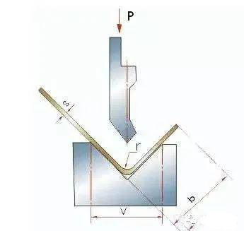
Im Allgemeinen kann die Arbeitstonnage gemäß der folgenden Tabelle bearbeitet und in den Verarbeitungsparametern eingestellt werden.
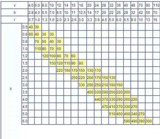
1. Der Wert in der Tabelle ist der Biegedruck bei einer Blechlänge von einem Meter:
Beispiel: S = 4 mm L = 1000 mm V = 32 mm
Schauen Sie in der Tabelle nach und erhalten Sie P = 330 kN
2. Diese Tabelle wird basierend auf dem Material mit der Festigkeit σb = 450N / mm2 berechnet. Beim Biegen anderer Materialien ist der Biegedruck das Produkt der Daten in der Tabelle und der folgenden Koeffizienten;
Bronze (weich): 0,5;
Edelstahl: 1,5;
Aluminium (weich): 0,5;
Chrom-Molybdän-Stahl: 2,0.
3. Ungefähre Berechnungsformel des Biegedrucks
P = 650s2L / 1000v
P - kn
S - mm
L - mm
V - mm
Biegedruckvergleichstabelle
B. Häufig auftretende Probleme beim Biegen von Blechen
1) Häufig verwendete Biegematrizen
Häufig verwendete Biegeform, wie unten gezeigt. Um die Lebensdauer der Form zu verlängern, sind die Teile so weit wie möglich mit abgerundeten Ecken versehen.
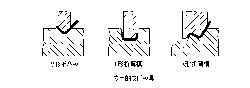
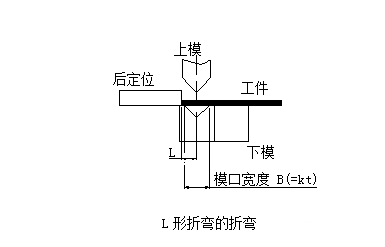
Wenn die Höhe des Flansches zu klein ist, ist selbst die Verwendung einer Biegematrize der Formgebung nicht förderlich. Im Allgemeinen beträgt die Flanschhöhe L ≥ 3 t (einschließlich Wandstärke).
Schrittverarbeitungsverfahren
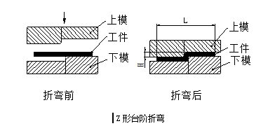
For some low-profile sheet metal Z-shaped step bending, processing manufacturers often use simple molds to process on punches or hydraulic presses, and small batches can also be processed on the bending machine with stepped die, as shown in the following figure. However, the height H should not be too high, generally should be (0 ~ 1.0) t, if the height is (1.0 ~ 4.0) t, it is necessary to consider the use of the mold form of the addition and discharge structure according to actual conditions.
The height of this mold step can be adjusted by adding shims, so the height H can be adjusted arbitrarily, but there is also a disadvantage that the length L size is not easy to guarantee, and the verticality of the vertical side is not easy to guarantee. If the height H size is large, it is necessary to consider bending on the bending machine.
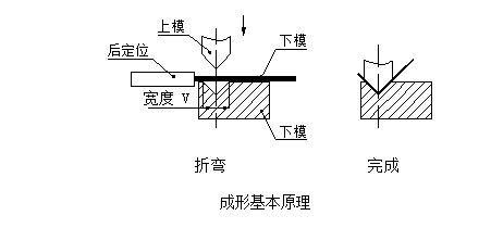
There are two types of bending machine: ordinary bending machine and CNC bending machine. Due to the high precision requirements and irregular bending shapes, the sheet metal bending of communication equipment is generally bent with a CNC bending machine. The basic principle is to use the bending knife (upper die) and V-groove (lower) of the bending machine. Die), bending and forming sheet metal parts.
Advantages: convenient clamping, accurate positioning and fast processing speed;
Disadvantages: low pressure, can only process simple forming, and low efficiency.
Basic principles of forming
The basic principle of forming is shown in the figure below:
Bending knife (upper die)
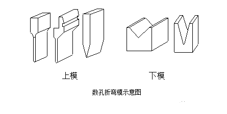
The form of the bending knife is shown in the figure below. It is mainly ed according to the shape of the workpiece during processing. Generally, there are many bending knife shapes of processing manufacturers, especially those with a high degree of specialization. In order to process various complex bending , Bending knives of many shapes and specifications are customized.
The lower die generally uses V = 6t (t is the material thickness) die.
There are many factors that affect the bending process, mainly including the radius of the upper die arc, material, material thickness, lower die strength, die size of the lower die and other factors. In order to meet the needs of the product, the manufacturer has already serialized the bending knife mold under the condition of ensuring the safety of the bending machine. We need to have a general understanding of the existing bending knife mold during the structural design process. See the figure below, the upper die is on the left and the lower die is on the right.
Basic principles of bending processing sequence:
(1) Bending from inside to outside;
(2) Bending from small to large;
(3) Bend the special shape first, and then bend the general shape;
(4) After the previous process is formed, it does not affect or interfere with the subsequent process.
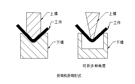
The current bending form is generally shown in the following figure:
2) Bending radius
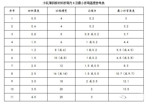
When bending sheet metal, a bending radius is required at the bending place. The bending radius should not be too large or too small, and should be ed appropriately. If the bending radius is too small, it is easy to cause cracking at the bending point, and if the bending radius is too large, the bending is easy to rebound. The preferred bending radius (inner bending radius) of various materials with different thicknesses is shown in the table below
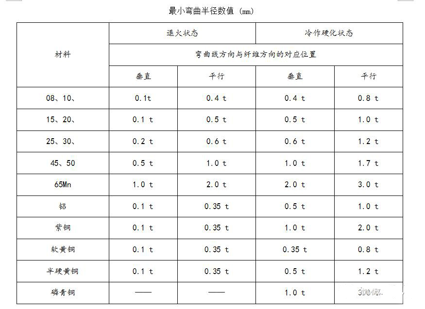
The data in the table above is the preferred data, for reference only. In fact, the corners of manufacturers' bending knives are usually 0.3, and a small number of bending knives are 0.5.
For ordinary low-carbon steel plate, rust-proof aluminum plate, brass plate, copper plate, etc., the inner fillet 0.2 is no problem, but for some high-carbon steel, hard aluminum, super hard aluminum, this bending round It will cause bending breakage or cracking of the outer corners.
3) Bending and rebound
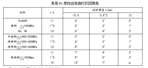
Springback angle Δα = b-a
Where b——the actual angle of the part after rebound;
a—The angle of the mold.
The size of the rebound angle
See the table below for the springback angle when a single angle is 90 ° free bending.
Factors affecting rebound and measures to reduce rebound
① The mechanical properties of the material The rebound angle is directly proportional to the yield point of the material and inversely proportional to the elastic modulus E. For sheet metal parts with high accuracy requirements, in order to reduce springback, the material should be ed as low-carbon steel as possible, not high-carbon steel and stainless steel.
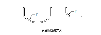
② The larger the relative bending radius r / t, the smaller the degree of deformation and the greater the rebound angle Δα. This is a relatively important concept. The rounded corners of sheet metal bending should be as small as possible, as long as the material properties allow, to improve accuracy. In particular, pay attention to avoid designing large arcs as much as possible, as shown in the following figure, such large arcs have greater difficulty in production and quality control:
4) Calculation of the minimum bending edge in one bending
The initial state of the L-shaped bend at the time of bending is shown below:
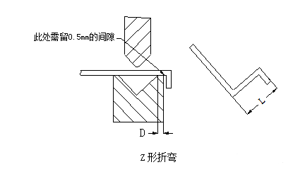
The initial state of the Z-shaped bending at the time of bending is shown in the figure below
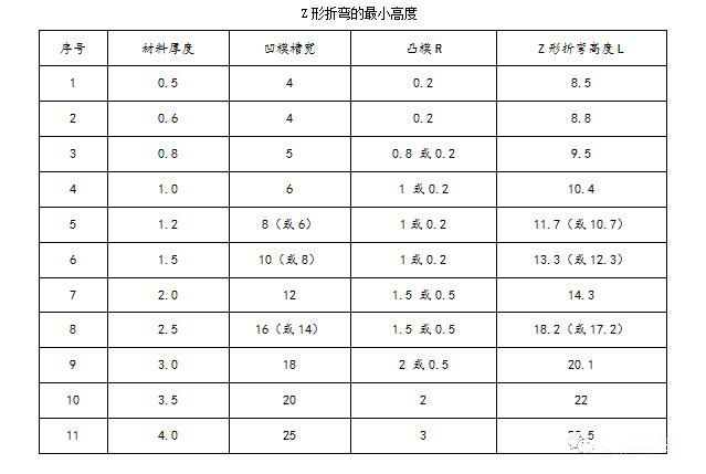
The minimum bending dimension L corresponding to the Z-bending of sheet metal with different material thickness is shown in the following table:
C. Fast calculation method of sheet metal bending and unfolding
When the sheet metal bending and flattening, one side of the material will be elongated and one side will be compressed. The factors affected are: material type, material thickness, material heat treatment and processing bending angle.
Expand calculation principle:
1) During the bending process, the outer layer is subjected to tensile stress and the inner layer is subjected to compressive stress. Between tension and compression, there is a transition layer that is neither tensile nor compressive, called the neutral layer; the neutral layer is bent during the bending process The length is the same as before bending, so the neutral layer is the benchmark for calculating the unfolded length of the bending piece.
2) The position of the neutral layer is related to the degree of deformation. When the bending radius is large and the bending angle is small, the degree of deformation is small. The position of the neutral layer is close to the center of the sheet thickness; when the bending radius becomes small, the bending angle increases When it is large, the degree of deformation increases accordingly, and the position of the neutral layer gradually moves to the inside of the bending center. The distance from the neutral layer to the inside of the sheet is expressed by λ.
On the other hand, with the emergence and popularization of computer technology, in order to make better use of the computer's super analysis and calculation capabilities, people increasingly use computer-aided design, but when computer programs simulate the bending of sheet metal Or it needs a calculation method in order to accurately simulate the process.
Although only to complete a certain calculation, each store can customize a specific program according to its original pinch rules, but nowadays, most commercial CAD and three-dimensional solid modeling systems have provided more general and Powerful solution.
In den meisten Fällen kann diese Anwendungssoftware auch mit den ursprünglichen erfahrungsbasierten und Finger-Pinch-Regeln kompatibel sein und eine Möglichkeit bieten, bestimmte Eingabeinhalte an den Berechnungsprozess anzupassen. SolidWorks ist natürlich führend bei der Bereitstellung dieser Blechkonstruktionsfunktion.

